
A4 Mk3
|
 WARNING
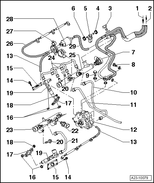
| 1 - | Fuel supply line |
| q | From fuel filter |
| 2 - | Fuel return line |
| q | To fuel tank |
| q | Fuel return line must not be kinked, damaged or clogged |
| 3 - | Banjo bolt for fuel return line |
| 4 - | Hose clip |
| 5 - | Fuel temperature sender -G81- |
| 6 - | Hose clip |
| 7 - | Fuel pressure regulating valve -N276- |
| q | Located on cylinder bank 1 |
| q | Cannot be re-installed |
| q | Removing and installing → Chapter |
| 8 - | Banjo bolt for fuel return line |
| q | 25 Nm |
| 9 - | Banjo bolt for fuel supply line |
| q | 25 Nm |
| 10 - | High-pressure fuel pipe |
| q | Between high-pressure pump and fuel rail on cylinder bank 1 |
| 11 - | High-pressure fuel pipe |
| q | Between fuel rail on cylinder bank 1 and fuel rail on cylinder bank 2 |
| q | When re-installing „high-pressure fuel pipe“, check taper seats visually for damage, scores and corrosion (always renew if damaged) |
| q | If they are to be re-installed, the injectors, high-pressure fuel pipe and clamping pieces must always be re-fitted in their original positions (i.e. on the same cylinder) |
| 12 - | High-pressure fuel pump |
| q | With fuel metering valve -N290- |
| q | High-pressure pump - exploded view → Chapter |
| q | Removing and installing → Chapter |
| 13 - | Fuel return lines (from injectors) |
| q | The fuel return lines must not be dismantled; if necessary they must be renewed complete with pressure retention valve |
| q | After replacement, engine must be run at idling speed for approx. 2 minutes to bleed fuel system. Then check fuel return lines for leaks |
| 14 - | Bolt |
| q | Cover for injector on cylinder head cover |
| q | 5.5 Nm |
| 15 - | Cover for injector |
| 16 - | Seal |
| 17 - | Clamping piece |
| q | If they are to be re-installed, the injectors and clamping pieces must always be re-fitted on the same cylinder. |
| q | When an injector is renewed, the corresponding clamping piece must be renewed at the same time. |
| 18 - | Hexagon flange nut |
| q | For clamping piece |
| q | 10 Nm |
| 19 - | Injector |
| q | Removing and installing → Chapter |
| 20 - | Bolt |
| q | 22 Nm |
| 21 - | High-pressure pipes |
| q | For cylinder bank 2 |
| q | 25 Nm |
| 22 - | Fuel pressure sender -G247- |
| q | 30 Nm |
| q | Located on cylinder bank 2 |
| q | Removing and installing → Chapter |
| 23 - | Fuel rail |
| q | For cylinder bank 2 |
| 24 - | High-pressure pipes |
| q | For cylinder bank 1 |
| 25 - | Fuel rail |
| q | For cylinder bank 1 |
| 26 - | Fuel return lines (from injectors) |
| q | The fuel return lines must not be dismantled; if necessary they must be renewed complete with pressure retention valve |
| q | After replacement, engine must be run at idling speed for approx. 2 minutes to bleed fuel system. Then check fuel return lines for leaks |
| 27 - | Retainer |
| q | For fuel return lines (from injectors) |
| 28 - | Pressure retention valve |
| q | In return lines from cylinder banks 1 and 2 |
| q | The pressure retention valve maintains a residual pressure of approx. 10 bar in the return lines |
| q | This residual pressure is required for the control function of the piezo injectors |
| q | The pressure retention valve may only be renewed together with the fuel return lines |
| q | After replacement, engine must be run at idling speed for approx. 2 minutes to bleed fuel system |
| q | Checking pressure retention valve → Chapter |
| 29 - | Fuel return line |
| q | Common return line to fuel tank |