-
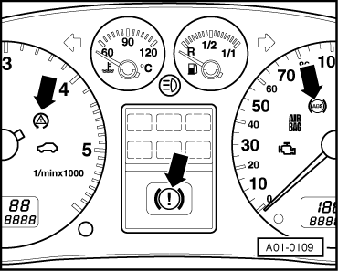
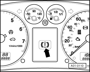
‒ ABS warning lamp -K47 lights.
-
‒ Traction control system/ESP warning lamp -K86 lights for 2 seconds and goes out again.
-
‒ Fault 01486 "System test active" is stored in fault memory.
-
‒ With vehicle stationary, press brake pedal with P = > 30 bar.
-
‒ EOL test is activated; traction control system/ESP warning lamp
-K86 flashes.
-
‒ Cornering should then be implemented within 20 seconds at v = 20...30 km/h. Test can be re-started by pressing brake pedal again with vehicle stationary.
-
‒ ASR/ESP and ABS lamps go out on successful completion of EOL test; system is OK.
Attention:
EOL test cannot be interrupted. "Normal" ABS operation can only be re-established after successfully completing EOL test.
Attention:
ABS/ESP/EBPD are not active when system is in diagnostic mode.
Danger of accident cannot be precluded if vehicle is driven after self-diagnosis has detected a fault.
The brake system is only functional to a limited extent. The rear wheels have a tendency to over-brake as the brake pressure at the rear wheels is no longer regulated by way of the electronic brake pressure distribution function. This causes the rear of the vehicle to break away.
If testers and measuring instruments are required during a test drive, these are always to be attached to the rear seat and operated from there by a second person.
If testers and measuring instruments were to be operated from front passenger's seat, person sitting there could suffer injury in the event of an accident due to triggering of front passenger's airbag.
If a complaint is received, pin-pointed fault finding must be performed as follows:
-
‒ First switch on ignition and observe warning lamps. The table in the Section "Description of warning lamp functions" => Page 01-50 provides an initial indication of what to look for.
-
‒ Pay attention to test requirements => Page 01-27.
-
‒ Connect up fault reader V.A.G 1551 and select "Brake electronics" with address word 03 => Page 01-4.
-
‒ Check control unit version => Parts List and press ⇒ key.
-
‒ Interrogate fault memory => Page 01-15.
-
‒ Conclude transfer of data with "End output" function => Page 01-16.
-
‒ Repair fault using fault table => Page 01-157. Select "Brake electronics" again with address word 03. Interrogate and erase fault memory.
-
‒ Conclude transfer of data with "End output" function. Disconnect fault reader V.A.G 1551.
-
‒ Check that connectors have been plugged in and engaged. Perform test drive => Page 01-19. The warning lamps should not come on during the test drive. Repeat fault-finding procedure if any warning lamps do come on.
Note:
If connector is not plugged into control unit when the vehicle is moving, a spurious fault may be registered in the fault memory of another control unit. The brake system is only functional to a limited extent. The rear wheels have a tendency to over-brake as the brake pressure at the rear wheels is no longer regulated by way of the electronic brake pressure distribution function. This causes the rear of the vehicle to break away. The danger of an accident cannot be precluded if vehicle is driven.
-
‒ Switch off ignition before performing assembly work. Establish code on vehicles with encoded radio and disconnect battery earth strap.
-
◆ Do not replace component indicated as being faulty before checking that wiring to component is OK. Wiring must be capable of transmitting the appropriate signals without interference. Check wiring for:
-
‒ Corrosion and loose contacts in connectors and earth connections. If contacts at connectors are bent, broken or corroded, use wiring harness repair set VAS 1978 to fit new contacts.
-
‒ Open circuits
-
‒ Short circuits to positive/earth
=> Current Flow Diagrams, Electrical Fault-finding and Fitting Locations binder
-
◆ Absolute cleanliness must be ensured when working on hydraulic unit. Thoroughly clean hydraulic pipe connections and surrounding areas. Do not use aggressive cleaning agents (e.g. brake cleaner, petrol, thinners) or any products which contain mineral oil, such as oils and greases. Do not unfasten hydraulic pipe connections until they have been cleaned.
-
◆ Place parts removed on a clean surface and cover them over. Do not use fluffy cloths.
-
◆ Only use genuine wrapped parts for replacement purposes. Leave replacement parts in their wrapping until immediately prior to installation.
-
◆ Bleed brake system after performing work involving opening of brake system.
=> Brake System; Repair Group 45; Exploded view of ESP components
-
◆ Welding work with an electric welding unit can affect the ABS/ESP system.
Test requirements
-
● Tyres of specified size and same make must be fitted on all wheels. Tyres must be inflated to correct pressure on all wheels.
-
● Mechanical/hydraulic components of brake system OK. No leaks in hydraulic connections and pipes (visually inspect hydraulic unit, brake calipers, wheel brake cylinders and tandem brake master cylinder).
-
● Wheel bearings and wheel bearing clearance OK.
-
● Speed sensor installation positions OK.
=> Brake System; Repair Group 45; Exploded view of ESP components
-
● Supply voltage OK (at least 10.0 V).
-
● Connector on ABS with EDL control unit -J104 properly attached; catch engaged.
-
● Self-diagnosis can only be started with vehicle stationary and ignition switched on (or engine running). Self-diagnosis cannot be started at wheel speeds in excess of 2.75 km/h.
-
● Whilst checking the ESP system, it must be ensured that the vehicle electrical system is not exposed to electromagnetic interference, i.e. the vehicle must not be in the vicinity of equipment with high power input, e.g. electric welding equipment.
Attention:
Diagnosis is not terminated at speeds of v = > 20km/h. Danger of accident.
|