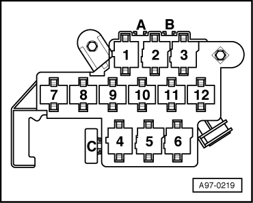
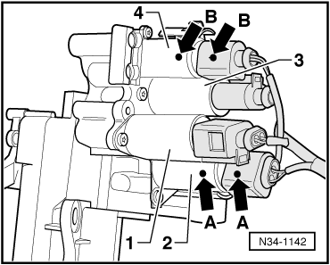
A2
| Test table |
| List of test steps |
| Component to be tested | Test step | ||
| Voltage supply and earth connection of electronic manual gearbox control unit -J514- |
| ||
| Selector lever lock solenoid -N110- |
| ||
| Switch for selector lever N-recognition -F258- |
| ||
| Switch for selector lever gate recognition -F257- |
| ||
| Switch for Stop recognition -F259- |
| ||
| Gearbox speed sender -G38- |
| ||
| Clutch travel sender -G162- |
| ||
| Gear selector valves -N284-, -N285-, -N286- and -N287- |
| ||
| Brake pressure switch -F270- |
| ||
| Potentiometer for selector lever, forwards/backwards -G272- |
| ||
| Lockout switch for diesel engine -F207- |
| ||
| Switch for Start/Stop mode -E262- (ECO mode) |
| ||
| Solenoid valve for ignition key removal lock -N334- |
| ||
| Hydraulic pump for clutch actuator -V180- |
| ||
| Valve for clutch actuator -N255- |
| ||
| Sender for gearbox hydraulic pressure -G270-, potentiometer 1 for gear recognition -G239- and potentiometer 2 for gear recognition -G240- |
| ||
| CAN bus wiring |
|
| Test step 1 |
| -V.A.G 1598/18- Sockets | Test of | Test requirements and operations | Specified value | Measures if readout does not match specification | ||||||||||||||
| 1 + 2 | Earth connection of electronic manual gearbox control unit -J514- |
| 0,0 Ω |
| ||||||||||||||
| 45 + 1 68 + 1 68 + 2 45 + 2 | Voltage supply for terminal 30 of electronic manual gearbox control unit -J514- |
| approx. battery voltage |
| ||||||||||||||
| 23 + 1 47 + 2 47 + 1 23 + 2 | Voltage supply for terminal 15 of electronic manual gearbox control unit -J514- |
| approx. battery voltage |
|
| Test step 2 |
| -V.A.G 1598/18- Sockets | Test of | Test requirements and operations | Specified value | Measures if readout does not match specification | |||
| 29 + 1 | Selector lever lock solenoid -N110- |
| |||||
| 0 V |
| |||||
| approx. battery voltage | ||||||
| 29 + 1 |
| ||||||
| Solenoid must click audibly, “Press brake” symbol lights up |
|
| Test step 3 |
| -V.A.G 1598/18- Sockets | Test of | Test requirements and operations | Specified value | Measures if readout does not match specification | ||||||
| Bridge between 29 + 1 | Switch for selector lever N-recognition -F258- |
| ||||||||
| 45 + 62 | ||||||||||
| approx. battery voltage |
| ||||||||
| 0 V |
| Test step 4 |
| -V.A.G 1598/18- Sockets | Test of | Test requirements and operations | Specified value | Measures if readout does not match specification | ||||||
| Bridge between 29 + 1 | Switch for selector lever gate recognition -F257- |
| ||||||||
| 45 + 39 | ||||||||||
| 0 V |
| ||||||||
| approx. battery voltage |
| Test step 5 |
| -V.A.G 1598/18- Sockets | Test of | Test requirements and operations | Specified value | Measures if readout does not match specification | ||||||
| Bridge between 29 + 1 | Switch for Stop recognition -F259- |
| ||||||||
| 45 + 41 | ||||||||||
| approx. battery voltage |
| ||||||||
| 0 V |
| Test step 6 |
| -V.A.G 1598/18- Sockets | Test of | Test requirements and operations | Specified value | Measures if readout does not match specification | ||
| 65 + 20 | Gearbox speed sender -G38- |
| ||||
| min. 0.7 kΩ |
| ||||
| max. 0.9 kΩ |
|
| Test step 7 |
| -V.A.G 1598/18- Sockets | Test of | Test requirements and operations | Specified value | Measures if readout does not match specification | ||||
| 50 + 28 | Clutch travel sender -G162- |
| ||||||
| min. 4.5 kΩ |
| ||||||
| max. 6.0 kΩ |
|
| Test steps 8.1 … 8.4 |
| -V.A.G 1598/18- Sockets | Test of | Test requirements and operations | Specified value | Measures if readout does not match specification | ||||||||||||
| 22 + 34 | Gear selector valve 1 -N284- |
| approx. 3 Ω → Note |
| ||||||||||||
| 33 + 46 | Gear selector valve 2 -N285- | approx. 3 Ω → Note | ||||||||||||||
| 53 + 67 | Gear selector valve 3 -N286- | min. 13 Ω → Note max. 14 Ω | ||||||||||||||
| 48 + 67 | Gear selector valve 4 -N287- | min. 13 Ω → Note max. 14 Ω |
| 4) | The specification refers to a temperature of approx. 20°C. If the valve temperature is above 20°C (gearbox hot), the resistance value of the valves increases. |
| Test step 9 |
| -V.A.G 1598/18- Sockets | Test of | Test requirements and operations | Specified value | Measures if readout does not match specification | ||||
| 15 + 1 | Brake pressure switch -F270- |
| ||||||
| ∞ Ω → Note |
| ||||||
| max. 2 Ω |
| 5) | Switch portable multimeter -V.A.G 1526 B- to largest Ω range. |
| Test step 10 |
| -V.A.G 1598/18- Sockets | Test of | Test requirements and operations | Specified value | Measures if readout does not match specification | |||||||
| 27 + 49 | Potentiometer for selector lever, forwards/backwards -G272- |
| |||||||||
| STOP | approx. 2.72 kΩ |
| |||||||||
| R | approx. 2.45 kΩ | ||||||||||
| N | approx. 2.19 kΩ | ||||||||||
| D or tiptronic gate | approx. 1.77 kΩ | ||||||||||
| Tiptronic to “+” | approx. 2.01 kΩ | ||||||||||
| Tiptronic to “–” | approx. 1.54 kΩ | ||||||||||
| 4 + 49 | STOP | approx. 1.45 kΩ | |||||||||
| R | approx. 1.72 kΩ | ||||||||||
| N | approx. 1.98 kΩ | ||||||||||
| D or tiptronic gate | approx. 2.42 kΩ | ||||||||||
| Tiptronic to “+” | approx. 2.17 kΩ | ||||||||||
| Tiptronic to “–” | approx. 2.65 kΩ | ||||||||||
| Test step 11 |
| -V.A.G 1598/18- Sockets | Test of | Test requirements and operations | Specified value | Measures if readout does not match specification | ||||||
| Bridge between 29 + 1 | Lockout switch for diesel engine -F207- |
| ||||||||
| 45 + 40 | ||||||||||
| approx. battery voltage |
| ||||||||
| 0 V |
| 6) | Before the test, the bridge must be connected using auxiliary wires from -V.A.G 1594 C- between sockets 29 + 1 to be able to move the selector lever. This cancels the locking of the selector lever by the selector lever lock solenoid -N110-. |
| Test step 12 |
| -V.A.G 1598/18- Sockets | Test of | Test requirements and operations | Specified value | Measures if readout does not match specification | ||||
| 45 + 63 | Switch for Start/Stop mode -E262- |
| ||||||
| 0 V |
| ||||||
| approx. battery voltage |
| Test step 13 |
| -V.A.G 1598/18- Sockets | Test of | Test requirements and operations | Specified value | Measures if readout does not match specification | ||||||
| Solenoid valve for ignition key removal lock -N334- |
| |||||||||
| Solenoid in ignition lock must click audibly |
| ||||||||
| 68 + contact 13 in relay plug |
| |||||||||
| approx. 8 Ω |
|

|
| Test step 14 |
| -V.A.G 1598/18- Sockets | Test of | Test requirements and operations | Specified value | Measures if readout does not match specification | ||||
| Hydraulic pump for clutch actuator -V180- |
| |||||||
| Pump starts up |
|
|

|
| Test step 15 |
| -V.A.G 1598/18- Sockets | Test of | Test requirements and operations | Specified value | Measures if readout does not match specification | ||
| 32 + 58 | Valve for clutch actuator -N255- |
| ||||
| approx. 6.5 Ω |
|
| Test step 16 |
| -V.A.G 1598/18- Sockets | Test of | Test requirements and operations | Specified value | Measures if readout does not match specification | ||
| 17 + 30 | Connection of sender for gearbox hydraulic pressure -G270-, potentiometer 1 for gear recognition -G239- and potentiometer 2 for gear recognition -G240- |
| ||||
| approx. 1 Ω |
| ||||
| 17 + 44 | Sender for gearbox hydraulic pressure -G270- and potentiometer 1 for gear recognition -G239- | approx. 290 Ω | Sender for gearbox hydraulic pressure -G270-, potentiometer 1 for gear recognition -G239- and potentiometer 2 for gear recognition -G240- are connected in parallel | |||
| 30 + 44 | Potentiometer 2 for gear recognition -G240- | approx. 290 Ω |
|
| Test step 17 |
| -V.A.G 1598/18- Sockets | Test of | Test requirements and operations | Specified value | Measures if readout does not match specification | ||
| 3 + 1 3 + 2 25 + 1 25 + 2 3 + 47 25 + 47 | CAN bus wiring |
| ||||
| ∞ Ω → Note |
|
| 7) | Switch portable multimeter -V.A.G 1526 B- to largest Ω range. |

