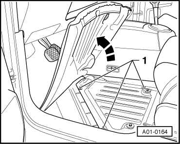
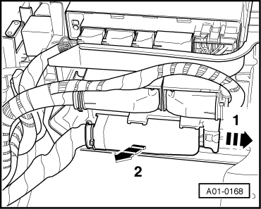
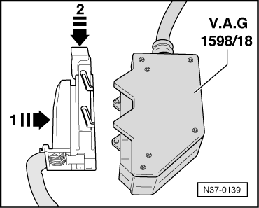
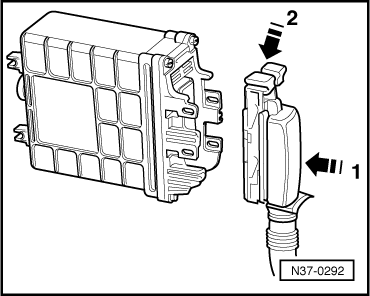
| 1 - | Earth (terminal 31) | 37 - | Potentiometer 1 for gear recognition -G239- signal |
| 2 - | Earth (terminal 31) | 38 - | Potentiometer 2 for gear recognition -G240- signal |
| 3 - | CAN low signal | 39 - | Switch for selector lever gate recognition -F257- |
| 4 - | Potentiometer for selector lever, forwards/backwards -G272- (supply voltage 5 V) | 40 - | Lockout switch for diesel engine -F207- |
| 5 - | Clutch travel sender -G162- signal | 41 - | Switch for selector lever Stop recognition -F259- |
| 6 - | Not used | 42 - | Not used |
| 7 - | Not used | 43 - | Gearbox speed sender -G38- (screening) |
| 8 - | Not used | 44 - | Earth for: |
| 9 - | Load shutoff relay -J511- | | | t
| Sender for gearbox hydraulic pressure -G270- |
|
| 10 - | Not used | | | t
| Potentiometer 1 for gear recognition -G239- |
|
| 11 - | Not used | | | t
| Potentiometer 2 for gear recognition -G240- |
|
| 12 - | Starter inhibitor and reversing light relay -J226- | 45 - | Supply voltage of terminal 30 |
| 13 - | Not used | 46 - | Gear selector valve 2 -N285- |
| 14 - | Sender for gearbox hydraulic pressure -G270- signal | 47 - | Supply voltage of terminal 15 |
| 15 - | Brake pressure switch -F270- | 48 - | Gear selector valve 4 -N287- |
| 16 - | Door contact switch signal | 49 - | Potentiometer for selector lever, forwards/backwards -G272- signal |
| 17 - | Supply voltage 5 V (bridge to pin 30) for: | 50 - | Supply voltage 5 V for clutch travel sender -G162- |
| | | t
| Sender for gearbox hydraulic pressure -G270- |
| 51 - | Engine cycle (monitoring signal for kick-down) |
| | | t
| Potentiometer 1 for gear recognition -G239- |
| 52 - | Not used |
| | | t
| Potentiometer 2 for gear recognition -G240- |
| 53 - | Gear selector valve 3 -N286- |
| 18 - | Start prompt from ignition/starter switch (terminal 50) | 54 - | Gearbox hydraulic pump relay -J510- |
| 19 - | TD-(speed) signal | 53 - | Not used |
| 20 - | Gearbox speed sender -G38- signal | 54 - | Not used |
| 21 - | Vehicle speed signal | 55 - | Not used |
| 22 - | Gear selector valve 1 -N284- | 56 - | Not used |
| 23 - | Supply voltage for terminal 15 (bridge to pin 47) | 57 - | Not used |
| 24 - | K-wires of diagnosis | 58 - | Valve for clutch actuator -N255- |
| 25 - | CAN high signal | 59 - | Reversing light switch -F4- |
| 26 - | Not used | 60 - | Not used |
| 27 - | Potentiometer for selector lever, forwards/backwards -G272- earth | 61 - | Not used |
| 28 - | Clutch travel sender -G162- earth | 62 - | Switch for selector lever N-recognition -F258- |
| 29 - | Selector lever lock solenoid -N110- | 63 - | Switch for Start/Stop mode -E262- |
| 30 - | Jumper to pin 17 | 64 - | Not used |
| 31 - | Not used | 65 - | Gearbox speed sender -G38- |
| 32 - | Valve for clutch actuator -N255- | 66 - | Not used |
| 33 - | Gear selector valve 2 -N285- | 67 - | Supply voltage for: |
| 34 - | Gear selector valve 1 -N284- | | | t
| Gear selector valve 3 -N286- |
|
| 35 - | Not used | | | t
| Gear selector valve 4 -N287- |
|
| 36 - | Not used | 68 - | Supply voltage of terminal 30 |


 Note
Note

 Caution